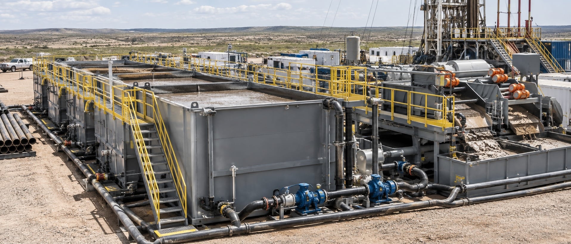
A useful solids control tank layout moves drilling fluid through defined removal, addition, and suction stages without unnecessary recirculation. Tank arrangement, flow routing, agitators, drainage, pump suction, access, and equipment placement all affect whether the system processes the returning fluid or repeatedly handles already-treated fluid.
A tank layout is more than a place to install equipment. It defines how fluid, solids, and pressure move between the return line, shale shaker, removal equipment, chemical-addition area, and mud-pump suction. A good layout makes the intended flow path visible and gives the crew access to operate, inspect, clean, and maintain each part of the system.
The layout supports the complete solids control equipment system. When a tank, pump, or return line creates a short path around a removal stage, rated equipment capacity does not guarantee useful solids removal.
Key takeaways
- Give each tank and pump a clear process role.
- Route fluid sequentially through removal stages where practical.
- Use agitators, baffles, and drainage features to limit dead zones and settled solids.
- Design for access, cleanout, inspection, and safe maintenance.
Start With the Process Flow
Begin the layout with the direction of returning fluid. The primary removal stage should receive the return flow before fluid moves into downstream tanks. From there, the system should carry fluid through the intended removal and treatment stages toward the addition and suction sections. Each pump should have a defined suction source and discharge destination.
Process flow becomes harder to control when several tanks share many transfer lines and every pump can pull from or discharge to multiple locations. Flexible routing can be useful during unusual conditions, but it can also make it difficult to verify where fluid is actually going. A simple design reduces valve-position errors and makes the operating configuration easier to understand.
Map the fluid path
- Identify the return point, primary shaker, removal tanks, addition area, and suction tanks.
- Mark each pump’s normal suction and discharge route.
- Show where hydrocyclone overflow, centrifuge discharge, and transfer flow enter the tanks.
- Identify equalizers, bypasses, and valves that can change the normal flow path.
- Review the map after a rig move, equipment change, or major drilling-condition change.
Avoid Short-Circuiting and Recirculation
Short-circuiting occurs when returning fluid bypasses a required removal stage or when treated fluid repeatedly returns to the same suction area instead of moving downstream. The result can be a system that appears busy but does not process the full incoming stream effectively. Separate the treatment steps clearly so the fluid progresses through the intended tanks.
Check pump discharge locations as carefully as pump capacity. A high-capacity pump can reduce processing efficiency if it returns cleaned fluid upstream or mixes untreated and treated fluid in the wrong compartment. The objective is not maximum movement between tanks; it is controlled movement through the correct sequence.
Check for unintended flow paths
During operation, observe tank levels, valve positions, return points, and the response of the suction section. If solids build despite active equipment, trace the flow from the return line to the mud pumps. A blocked line, open bypass, incorrect valve, or poorly placed discharge may be the cause.
Tank Geometry, Agitators, and Drainage
Tank geometry affects how fluid and solids move. Corners, flat low points, internal piping, and poorly mixed compartments can create dead zones where solids settle. Effective agitation and a sufficient turnover rate help keep material suspended until removal equipment can process it. Agitators should support the actual tank volume and flow pattern rather than simply create local motion near the motor.
Design for easy drainage and cleanout. Sloped or shaped bottoms, accessible low points, properly located drains, and clear access around internal components make tank maintenance more manageable. A tank that is difficult to drain or inspect can retain solids that later return to the active system.
Layout inspection checklist
- Identify low points, corners, baffles, and areas beneath fixed equipment.
- Check whether agitators support circulation across the full tank.
- Confirm drains, suction points, and cleanout access are reachable.
- Inspect internal piping and supports for places where solids can collect.
- Record recurring buildup locations after each cleanout.
Protect the Suction and Addition Sections
The suction section supplies the mud pumps, so it needs well-mixed fluid and a stable level. Avoid placing a direct return, uncontrolled transfer, or high-solids discharge where it can immediately affect pump suction. Give the fluid sufficient path and mixing before it reaches the suction connection.
Keep the addition section distinct from the main removal path when the process requires it. Additives, dilution, and weighting materials need controlled mixing and observation. A layout that combines all functions in one tank can make it harder to separate solids, maintain fluid properties, and troubleshoot a change in performance.
Consider pressure and pump behaviour
Pump suction conditions affect more than flow. Restricted lines, low levels, air entry, or poor tank mixing can cause unstable pressure and poor equipment performance. Review the tank layout whenever a pump loses stable suction, a transfer rate changes, or a new piece of equipment is added.
Design for Access, Maintenance, and Cleaning
A layout should give the crew room to inspect equipment, reach valves, observe flow, service agitators, and clean settled material. Platforms, walkways, lighting, guards, hose routing, and drain access all influence whether normal maintenance can be completed safely and consistently. Do not place a critical valve or inspection point where the crew cannot see or reach it during normal operation.
The mud tank cleaning best practices field workflow explains why cleanout access, isolation planning, and waste handling need to be considered before a tank is in service. Good layout decisions reduce the frequency and difficulty of tank cleaning.
Connect Layout to Equipment Performance
Each solids-control device depends on the layout around it. A shale shaker needs an appropriate return flow. Hydrocyclones need stable pump feed and a suitable suction tank. A centrifuge needs a predictable feed and discharge route. The solids control equipment safety practices guide provides related context for access, guarding, isolation, and operating hazards around those connections.
Review capacity considerations alongside routing. Extra equipment capacity cannot correct a layout that sends fluid around the intended process. Before adding pumps or tanks, verify whether a simpler change in discharge location, valve arrangement, line routing, or agitation can improve the existing design.
Review the Layout During Service
A tank layout should be reviewed as operating conditions change. A different well section, higher circulation rate, new drilling fluid, longer return line, altered rig position, or added piece of equipment can change the flow pattern that the original layout supported. The drawing may remain the same while actual conditions in the tanks change substantially.
Use normal rounds to compare the intended flow path with the real one. Observe where fluid enters each tank, whether agitators create useful circulation, where solids collect, and how the suction section responds to transfer flow. Check accessible drains, line supports, hose routing, and valve identification. These observations can reveal a developing layout problem before it appears as poor solids removal, unstable pump performance, or a difficult cleanout.
Document the operating layout
Keep a current diagram or log that identifies normal flow, temporary changes, valve positions, and equipment taken out of service. Clear documentation helps the crew restore the correct configuration after maintenance and reduces the chance that a temporary routing change becomes an unnoticed operating condition.
Frequently Asked Questions
Why can a high-capacity system still have poor solids removal?
Rated equipment capacity does not prove that returning fluid passes through the equipment in the intended sequence. Short-circuiting, recirculation, poor suction routing, and bypasses can reduce actual processing efficiency.
What creates dead zones in mud tanks?
Corners, flat low points, internal obstructions, weak agitation, poor turnover, and unsuitable flow paths can allow solids to settle. Inspect recurring buildup locations and adjust the layout or operating practice where practical.
Why does tank layout affect pump performance?
Pumps need a stable, well-mixed fluid supply. Low tank levels, restricted suction, air entry, poor circulation, and incorrect return locations can disrupt suction and affect pressure and flow.
When should a tank layout be reviewed?
Review the layout after a rig move, equipment addition, major drilling change, recurring solids buildup, pump-suction issue, or unexpected reduction in solids-control performance.