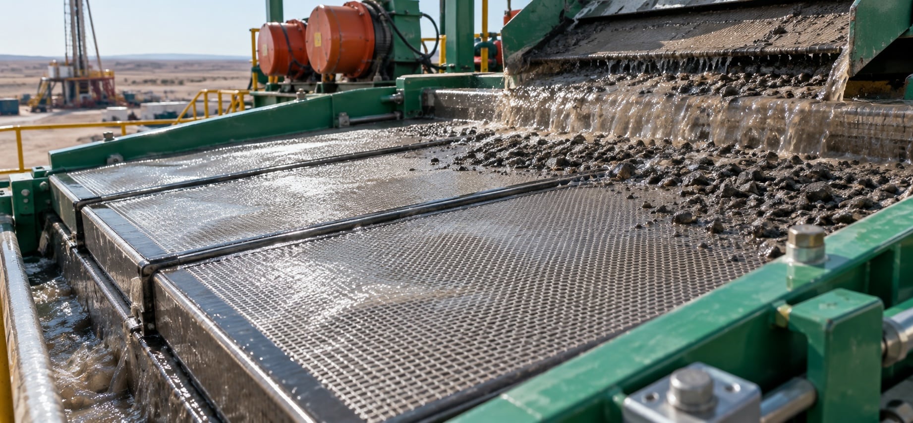
This shale shaker screen selection guide helps field teams choose screens that match the shale shaker, drilling conditions and solids-control targets. The right screen affects cuttings removal, fluid recovery, screen life and downstream equipment performance, so selection is more than picking a mesh number.
Start by confirming fitment and deck compatibility, then compare API designation, conductance and separation range against the formation and mud system. A practical screen choice balances solids removal with usable flow capacity, helping crews maintain stable performance without unnecessary screen changes or costly fluid losses.
Key takeaways
- Match API-rated separation to flow capacity; the finest screen is not always the best operational choice.
- Verify panel dimensions, hook geometry, deck supports, tensioning, and seals before installing replacement screens.
- Usable open area and conductance can differ significantly between screens with similar API designations.
- Monitor pooling, blinding, fluid loss, solids bypass, and discharge dryness to adjust screens as conditions change.
- Inspect deck rails, clamps, seals, mesh, and frames regularly; poor fitment causes bypass and premature failure.
- Record screen changes, flow rate, mud condition, and operating hours to improve future selection decisions.
Shale Shaker Screen Selection Guide: What Shaker Screens Affect
A practical shale shaker screen selection guide starts with a simple point: shaker screens do far more than separate cuttings from drilling fluid. The shale shaker sets the first stage of solids control, influencing fluid quality, downstream equipment loading, waste volumes, and the consistency of daily drilling operations. Because the shale shaker handles the highest-volume stream in the system, even a modest change in screen selection can affect the entire mud-cleaning process.
The right screen must balance separation efficiency with usable fluid capacity. A finer mesh can remove smaller solids, helping protect mud properties and reducing the burden on desanders, desilters, and centrifuges. But if that screen does not provide sufficient conductance for the flow rate, fluid may pool on the deck, bypass the screening surface, or be lost with discarded solids. A coarser screen may process more fluid without flooding, yet allow more drilled solids to remain in the active system. Neither choice is automatically correct; the best selection reflects the formation, flow rate, drilling phase, mud weight, and the shaker’s motion and deck configuration.
- Finer screens: Improve removal of smaller solids but may reduce fluid capacity.
- Coarser screens: Support higher flow rates but may leave more drilled solids in the system.
- Screen fit and construction: Affect sealing, wear, tension, and reliable screening performance.
Screen construction also matters. API screen designation provides a consistent way to compare separation potential, while the actual usable area, wire cloth arrangement, bonding method, and frame design affect how a screen performs in operation. A screen that fits the shaker securely and maintains proper tension is less likely to leak, wear unevenly, or fail prematurely. Using an incompatible replacement can compromise both screening control and equipment reliability, even when its nominal mesh appears suitable.
Effective selection is therefore an operating decision, not a one-time purchasing choice. Crews should watch fluid flow across the screen, solids discharge, mud losses, screen life, and the condition of downstream fluid-control equipment. If screens blind, tear, overload, or consistently run with excessive fluid at the discharge end, the current setup deserves review. Matching shaker screens to real drilling conditions helps the solids-control system remove unwanted material early, retain valuable drilling fluid, and keep the operation stable as conditions change.
Screen Selection Checklist
- Match API screen designation to the target separation range and drilling-fluid requirements.
- Confirm conductance can handle current flow rates without pooling, bypass, or excessive mud loss.
- Consider formation, drilling phase, mud weight, shaker motion, and deck configuration before changing screens.
- Verify replacement screens fit securely and maintain proper tension across the shaker deck.
- Inspect wire cloth, bonding, frame construction, and usable area alongside nominal mesh rating.
- Monitor solids discharge, fluid coverage, screen blinding, tears, and wear during operation.
- Review downstream equipment loading; excess fine solids may signal that screening needs adjustment.
Confirm Shaker Screen Fitment, Screen Deck and Compatibility
A shaker screen can only perform as intended when its dimensions, mounting system and screen deck match the shaker. Confirm the screen area, panel profile and tensioning method before ordering. Size selection is not only about length and width: the screen design must suit the deck support pattern and the material being processed. Check the equipment manual and compare its specifications with the supplier’s compatibility data.
Hook Strip Screen Panel Fitment and Sealing Checks
A hook strip screen panel must match the shaker’s rated dimensions and hook geometry precisely. Measure the panel’s overall length and width, then verify hook width, return angle and strip position against the existing screen or the manufacturer’s drawing. Small differences can prevent the panel from seating squarely, even when the stated shaker screen size appears correct.
Inspect the screen deck before fitting a replacement. Deck rails, crown bars and support members should be clean, straight and free of hardened buildup. A bent rail, worn tensioning bar or damaged clamp can leave part of the screen unsupported. This reduces usable screen area and may allow the mesh to flex excessively, shortening service life or causing early tears.
During installation, engage both hook strips evenly and apply tension according to the shaker manual. The panel should lie flat across the deck without wrinkles, raised corners or loose sections. Run a hand carefully over the surface to identify gaps between the screen and its supports. Any open space can allow vibration to concentrate in one area instead of being distributed across the screen design.
Sealing matters as much as mechanical fit. Check side seals, end seals and interfaces around the frame for routes through which solid particles could bypass the mesh. A properly fitted shaker screen directs material through the intended openings; poor seals let oversized solids pass downstream and undermine separation performance. After startup, inspect for material trails, unusual noise or localized wear. These signs often point to an alignment, tensioning or deck-contact issue that should be corrected before the screen is put into regular service.
API Designation, Mesh Sizes and Particle Size
API designations provide a consistent way to compare mesh sizes and expected particle separation. The designation relates to the opening distribution of a mesh screen rather than a simple count of openings, so it offers a more useful reference for screen selection. In practice, the right screen must remove fine particles efficiently while maintaining the fluid capacity the shaker needs.
How Screen Design Balances Screen Area and Fluid Handling
Effective screen design is a balance between separation performance and the ability to process drilling fluid without flooding the shaker. A finer screen captures smaller solids from the returning fluid, but its smaller openings can restrict flow. If the available screen area is too low for the circulating rate, fluid may pool on the deck, bypass the mesh, or carry usable liquid away with the shale.
Usable screen area matters more than the outside dimensions of a panel. Frame construction, support layers, bonding patterns, and the shape of the mesh can all reduce the open area available for screening. Modern shaker screens often use layered mesh and corrugated or wave-style designs to increase effective area within the same footprint. That added area can improve fluid handling while retaining a fine separation point.
Screen selection should also reflect the drilling conditions. High flow rates, heavier mud weights, reactive shale, and elevated solids loading place greater demand on the screen. Running the finest possible screen is not always the best choice if it causes excessive fluid loss or frequent blinding. Instead, choose a mesh that maintains a stable fluid pool, conveys solids reliably, and produces a manageable volume of discharged cuttings.
Operators can refine the setup by observing fluid distribution across the screen, solids dryness, and signs of overload. Screen angle, shaker motion, and flow control affect performance alongside the screen itself. A sound design keeps drilling fluid moving through the mesh while directing separated solids off the shaker before they can interfere with further screening.
Screen Selection Factors for Balancing Separation and Fluid Handling
| Operating factor | What it can affect | What to observe during operation |
|---|---|---|
| Mesh fineness | Finer mesh captures smaller solids but can restrict fluid flow and increase the risk of blinding or fluid loss. | Fluid distribution, solids dryness, fluid loss with discharged shale, and signs of blinding. |
| Usable screen area | Insufficient open area for the circulating rate can cause fluid pooling, mesh bypass, or liquid carryover with shale. | Fluid pooling on the deck, bypass around the mesh, and discharged cuttings containing usable liquid. |
| Screen frame, support layers, bonding, and mesh shape | These design features can reduce open area or, with layered and corrugated designs, increase effective area within the same footprint. | Fluid handling capacity, stable fluid pool, and whether flow moves through the mesh without overload. |
| Circulating flow rate | Higher flow rates place greater demand on screen capacity and can overload screens with limited usable area. | Fluid distribution across the screen, deck pooling, mesh bypass, and signs of overload. |
| Mud weight and solids loading | Heavier mud and elevated solids loading increase screening demand and may make an overly fine mesh impractical. | Stable fluid pool, solids conveyance, cuttings volume, and frequent blinding. |
| Reactive shale | Reactive shale can contribute to screen blinding and interfere with reliable solids removal. | Signs of blinding, fluid flow through the mesh, and consistency of solids discharge. |
| Screen angle, shaker motion, and flow control | These settings influence fluid movement, solids conveyance, and overall screening performance alongside mesh selection. | Fluid distribution, stable fluid pool, solids dryness, and whether separated solids move off the shaker reliably. |
Selecting Shaker Screens for Drilling Conditions
Selecting shaker screens begins with the solids-control objective, not simply the finest mesh size available. A shale shaker is the first major separation point in a drilling operation, and its screens must remove unwanted solids while retaining enough usable drilling fluid to support stable, efficient circulation. The right choice depends on the formation being drilled, the expected particle size distribution, flow rate, fluid properties, and the condition of the equipment itself. A screen that is too coarse can allow abrasive solids to recirculate, increasing wear on pumps, lines, and downstream equipment. One that is too fine may restrict fluid handling, cause excessive screen loading, and send valuable fluid over the discharge end with the cuttings.
Start by matching mesh size and API designation to the solids profile and the capacity of the shaker. Screen selection should account for conductance as well as separation point: two screens with a similar API rating can process fluid differently because of their usable open area and panel design. Higher flow rates, heavier drilling fluid, reactive shale, or elevated low-gravity solids may require a screen arrangement that maintains throughput without frequent blinding. Operators commonly use a staged approach, fitting finer screens where the fluid can support them and adjusting as drilling conditions change.
Fluid type also matters. Water-based systems, oil-based mud, and dense slurry can behave very differently across a vibrating screen. Viscosity, temperature, chemical treatment, and solids loading all affect how readily fluid passes through the cloth. In applications involving slurry transfer, confirm that the slurry pump, tank volume, and feed distribution provide a steady supply to the shaker; surging or uneven flow can overload one area of the screen and reduce separation efficiency. Proper deck angle, vibration settings, and screen tension are equally important because even a well-chosen panel will underperform when installed or operated incorrectly.
Monitor the discharge and recovered fluid during the operation rather than treating screen selection as a one-time decision. Signs of overloaded screens include:
- Pooling
- Rapid blinding
- Excessive fluid loss with cuttings
- Solids bypass
Inspect panels for tears, worn edges, poor seals, and damaged frames, since a small failure can compromise the entire solids-control system. By balancing particle size removal, fluid recovery, and screen capacity, crews can protect drilling equipment, reduce dilution and disposal costs, and maintain more consistent drilling performance.
Screen Selection Checklist
- Match API screen designation to the expected solids profile, rather than automatically choosing the finest available mesh.
- Compare conductance and usable open area; similarly rated screens can deliver substantially different fluid-processing capacity.
- Adjust screen arrangements for flow rate, mud weight, viscosity, reactive shale, and rising low-gravity solids.
- Use staged screening: run finer panels when fluid conditions allow, then revise selections as drilling conditions change.
- Maintain steady shaker feed from slurry pumps and tanks; surging can overload panels and reduce separation efficiency.
- Verify deck angle, vibration settings, tension, seals, and frame condition before diagnosing a screen-selection problem.
- Monitor pooling, blinding, fluid loss with cuttings, and solids bypass; inspect panels promptly for tears or worn edges.
Screen Selection Workflow and Field Guidelines
Effective screen selection starts with the drilling objective, the current solids-loading condition, and the capability of the shaker system, not simply the finest mesh available. Review the fluid type, expected formation characteristics, flow rate, mud weight, and the volume of solids reaching the shaker. These factors determine whether the priority is maximum solids removal, reliable fluid recovery, screen life, or a balanced result across all three. A screen that performs well in one interval may be unsuitable after a change in lithology, penetration rate, or drilling-fluid properties.
Begin by confirming the shaker screen model and the screen deck configuration approved for the equipment. Screen dimensions, fastening method, deck angle, motion type, and available vibration control all affect usable capacity. Use the manufacturer’s manual as the primary guide for compatible screen types and installation requirements. A properly matched screen must seal correctly against the deck; gaps, damaged gaskets, or an incorrectly tensioned panel allow solids to bypass the separation surface and undermine the selection.
Choose an API-rated screen based on the separation needed while preserving adequate conductance for present flow conditions. When the shaker approaches overflow, first inspect feed distribution, fluid properties, deck angle, and screen condition before automatically moving to a coarser screen. Conversely, if fluid is leaving the shaker with excessive drilled solids, evaluate whether a finer screen can be used without reducing processing capacity below operational demand. Step changes in screen selection are often more practical than large jumps, particularly when conditions are changing quickly.
Field guidelines should include routine visual checks for blinding, plugging, torn cloth, delamination, and uneven solids coverage. Record the screen designation, operating hours, flow rate, mud condition, and reason for each change. This creates a useful operating history and helps distinguish a screen failure from a control, hydraulic, or solids-management issue elsewhere in the system. Maintain clean spare screens in the required range, install them carefully, and replace damaged panels promptly. Consistent selection and disciplined inspection protect downstream equipment, support stable mud properties, and keep shaker operations predictable.
Screen Selection Checklist
- Confirm drilling objectives, solids loading, fluid type, flow rate, mud weight, and expected formation characteristics.
- Verify approved screen model, deck configuration, dimensions, fastening method, motion type, and installation requirements.
- Select an API-rated screen that balances solids removal, fluid recovery, screen life, and available conductance.
- Inspect feed distribution, fluid properties, deck angle, and screen condition before changing to a coarser mesh.
- Use smaller screen-selection changes when drilling conditions, lithology, penetration rate, or fluid properties shift.
- Check routinely for blinding, plugging, torn cloth, delamination, damaged gaskets, and uneven solids coverage.
- Record screen designation, operating hours, flow rate, mud condition, and reasons for every screen change.
Troubleshoot Shaker Screen Performance and Buy Equivalent Replacements
When a shaker screen stops delivering clean fluid and manageable solids, the cause is not always a damaged panel. Start by checking how the screen is operating in the shaker: confirm the deck is secure, tension is correct, and the screen is seated without gaps that allow fluid or particles to bypass the mesh screen. Inspect for torn cloth, broken bonding, plugged openings, excessive wear along the edges, and blinding caused by fine solids. These issues can reduce screening capacity even when the screen appears intact.
Screen performance also depends on conditions upstream. A heavy solids load, inconsistent flow, unsuitable fluid properties, or poor tank management can overload the shaker. Watch the solids pattern across the screen. Material building at the feed end may indicate excessive flow or inadequate distribution, while solids carried off the discharge end can point to an overly coarse mesh size, worn mesh, or screen selection that does not suit the formation and drilling program. Fine particles passing into the tank may require a finer screen design, provided the shaker can maintain fluid handling capacity.
For replacement shaker screens, match the functional requirements rather than relying only on a familiar product name. Verify the panel dimensions, hook style or fastening method, frame construction, usable screening area, and the manufacturer’s mesh rating system. Mesh sizes alone are not always directly comparable between brands; wire diameter, weave, layer configuration, and API classification affect separation performance. An equivalent screen should fit the shaker properly, withstand expected vibration, and provide the conductance and cut point needed for the operation.
Before placing an order, record the existing screen part number where available, measure the frame, identify the shaker model, and note the application: fluid type, expected solids volume, target particle removal, and current screen life. This information makes replacement selection more reliable and helps avoid buying a screen that fits physically but performs poorly. If screen failures recur, review installation, storage, cleaning practices, and shaker settings alongside the replacement choice. A better screen design can improve results, but consistent screening depends on the full solids-control system working together.
Screen troubleshooting checklist
- Confirm the deck is secure, tension is correct, and the panel seats tightly without bypass gaps.
- Inspect for torn cloth, failed bonding, plugged openings, edge wear, and fine-solids blinding.
- Check solids distribution: feed-end buildup may signal overload, while discharge carryover can indicate overly coarse screening.
- Review upstream conditions, including flow consistency, solids loading, fluid properties, and tank management.
- Match replacements by shaker model, dimensions, hook style, frame construction, usable area, and fastening method.
- Compare API classification, conductance, cut point, wire diameter, weave, and layer configuration, not mesh number alone.
- Record the current part number, application details, target separation, and screen life before ordering replacements.
Frequently asked questions
How do I choose the right shale shaker screen mesh size?
Choose an API-rated screen that achieves the needed solids removal while maintaining enough conductance for the current flow rate, mud weight, fluid type, and solids loading. The finest screen is not always best if it causes pooling, blinding, overflow, or excessive fluid loss with cuttings.
What does an API screen designation mean?
An API designation is a standardized classification for a shaker screen’s particle-separation capability. It is more useful than mesh count alone because it reflects the opening distribution of the screen cloth. Compare API ratings together with conductance, usable area, and panel construction.
Can I use an equivalent replacement shaker screen from another brand?
Yes, provided it is truly compatible with the shaker. Confirm panel length and width, hook strip or fastening style, frame profile, deck support pattern, seals, API rating, usable screen area, and expected conductance. A panel that fits physically may still perform differently from the original.
Why is drilling fluid going over the end of the shaker screen?
Common causes include a screen that is too fine for the flow, restricted or blinded mesh, high solids loading, uneven feed distribution, heavy or viscous mud, incorrect deck angle, or unsuitable vibration settings. Inspect these conditions before moving immediately to a coarser screen.
What causes shaker screens to blind or plug?
Blinding occurs when fine, sticky, reactive, or coated solids block screen openings. It may also result from high mud viscosity, chemical changes, excessive loading, poor fluid distribution, or damaged cloth. Review fluid properties and operating conditions as well as the screen selection.
How can I tell if a shaker screen is installed correctly?
The screen should sit flat, engage evenly with the tensioning system, and seal around the deck without wrinkles, raised corners, gaps, or loose areas. Inspect deck rails, crown bars, clamps, and gaskets first. Material trails, unusual noise, and localized wear can indicate poor fitment or tension.
When should shale shaker screens be changed?
Replace screens when they tear, delaminate, lose tension, develop worn edges, blind repeatedly, or allow solids bypass. Also review the screen setup when formation conditions, flow rate, mud properties, or solids loading change enough to affect fluid recovery and separation performance.