Understanding the nature of drilled solids to be encountered during a drill is critical for determining the optimal mud recycling system. Depending on the anticipated geology of an area, different means of mechanical separation are required. The source of the solids determines the particle sizes entrained in the drilling fluid slurry. These particles range in size from 1 micron to larger cuttings greater than 440 microns. It is very important to reference the source of the solids when choosing the type of mud recycling equipment required for a particular job. Figure 1 below shows the API classification for particle sizes commonly encountered on HDD projects.
| Aggregate Name | API Classification | Size Range (metric) Note: 1000 microns = 1mm | HDD Mud Recycling Equipment |
| Cobble | Coarse | 64 – 256 millimeters (mm) | Shaker |
| Gravel | Coarse | 2 – 64 millimeters (mm) | Shaker |
| Coarse Sand | Intermediate | 0.5 – 2 millimeters (mm) | Desander (Mud Cube) |
| Sand | Medium | 74 – 500 microns (µ) | Desander (Mud Cube) |
| Silt | Ultra-fine and Fine | 4 – 74 microns (µ) | Centrifuge |
| Clay | Colloidal | 1 – 4 microns (µ) | Centrifuge |
| Colloids | Colloidal | <1 microns (µ) | Polymer Assisted Centrifuge |
Figure 1: API Classification of soil particle sizes and the required HDD Mud Recycling Equipment required for removal.
Colloids
It is also noteworthy that drilling fluids by design contain commercial additives such as bentonite solids that have a particle size less than 1 micron. These chemical additives make up the colloidal end of the particle size spectrum and to an extent some are desirable for developing a thin, slick cake on the borehole wall. However, there is a point where a build-up of colloids causes an undesirable increase in viscosity. Colloids can be removed from the drilling fluid by combining polymer additives with a centrifuge. The process of removing colloids is called “mud stripping” and is done at the end of the drill to separate the commercial additives from the original source water.
Geological Reports
Before an HDD bore is ever done a geological report is created by drilling test holes along the length of the proposed installation. Subsurface geology changes along the course of a proposed bore hole as differences in subsurface rock strata and soil sequencing are encountered. By referencing the geological report prior to the project starting, it is possible to determine which mechanical separation equipment will be required during the drilling process.
Optimization with a Particle Size Analyzer
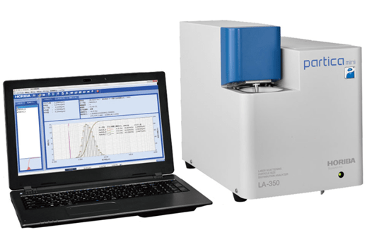
To extract the most value possible from a mud recycling system, further due diligence is required once drilling gets started. Getting the right equipment on site is only the first step in delivering a quality drilling fluid recycling system. Samples should be taken throughout the course of the drill and assessed using a particle size analyzer (PSA). The information provided from the PSA enables the drilling fluid technicians to optimize the shakers, mud cubes (desanders), and centrifuges such that all entrained soils are removed. By altering screen sizes, equipment speeds and chemical additives, optimized drilling fluid recycling can be achieved. Figure 3 shows PSA results from a sample taken along an HDD borehole. This section of the drill constituted silt and clay of which 90% of the particles were smaller than 20 microns.
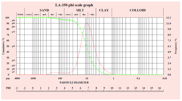
Figure 3: Data supplied by an onsite PSA showing that 90% of the particles less than 20 microns and 50% of the particles smaller than 9 microns. In this case, centrifuges are the only method for recycling the drilling fluid.
Conclusion
In HDD drilling, it is immediately obvious that the geology of the drilled formation will have a direct impact on selecting the proper tooling and drilling fluid for the job. Equally important however is using this geological information to ensure the correct mud recycling equipment is on site.